Adding underlighting to Lily58 keyboard
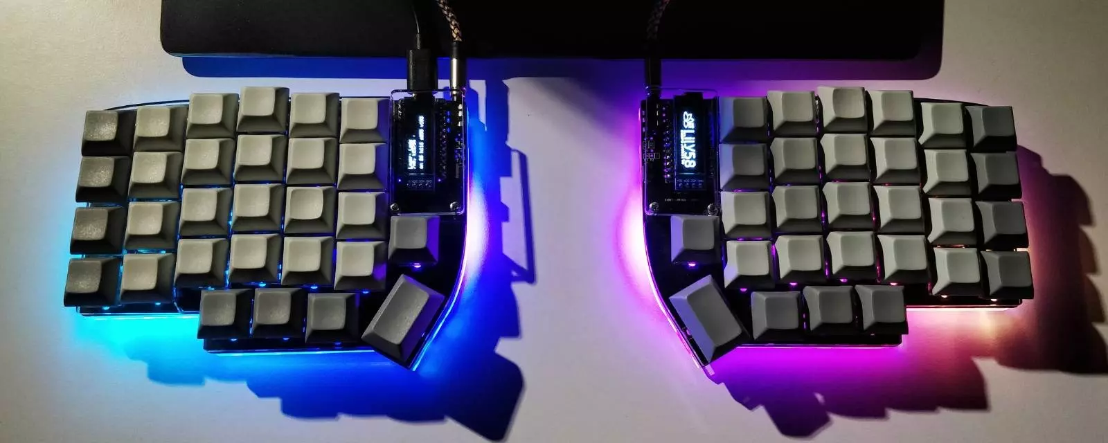
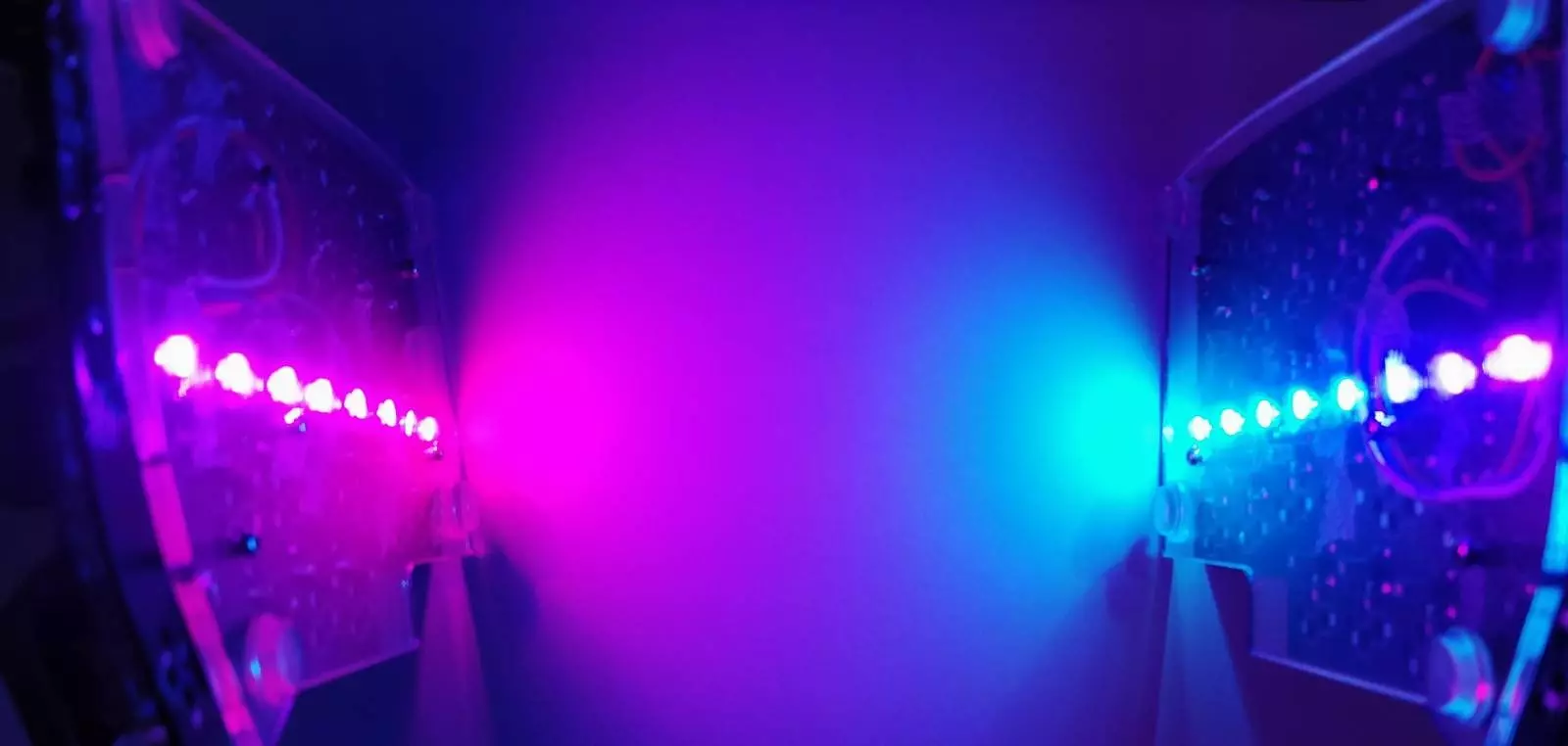
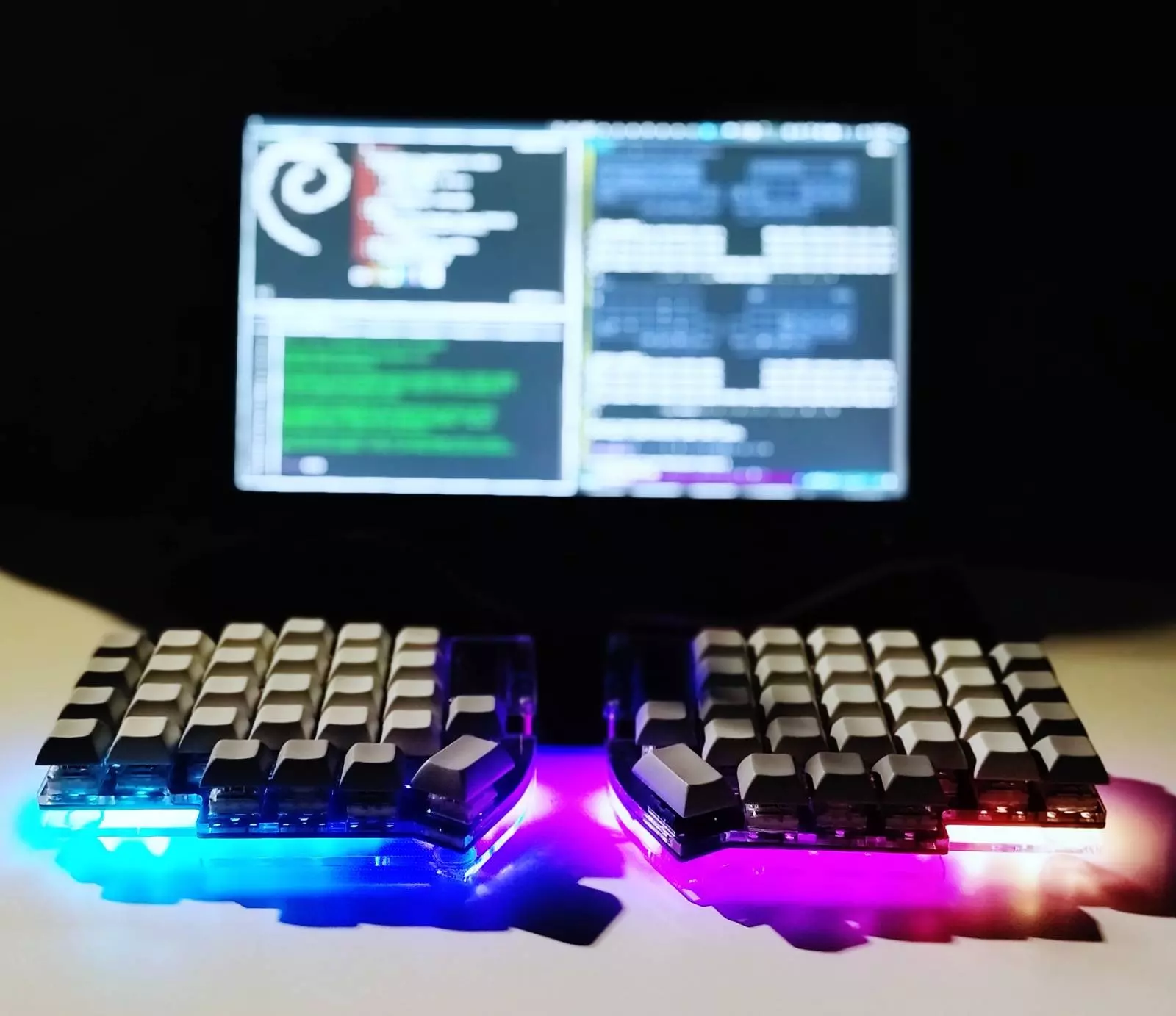
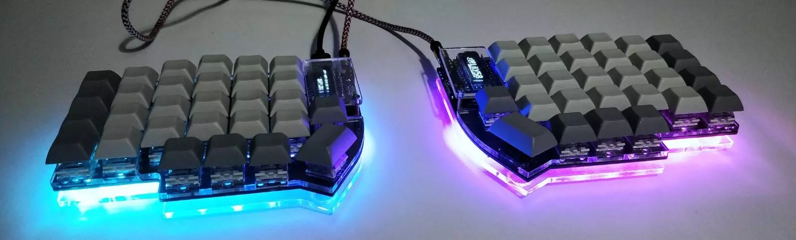
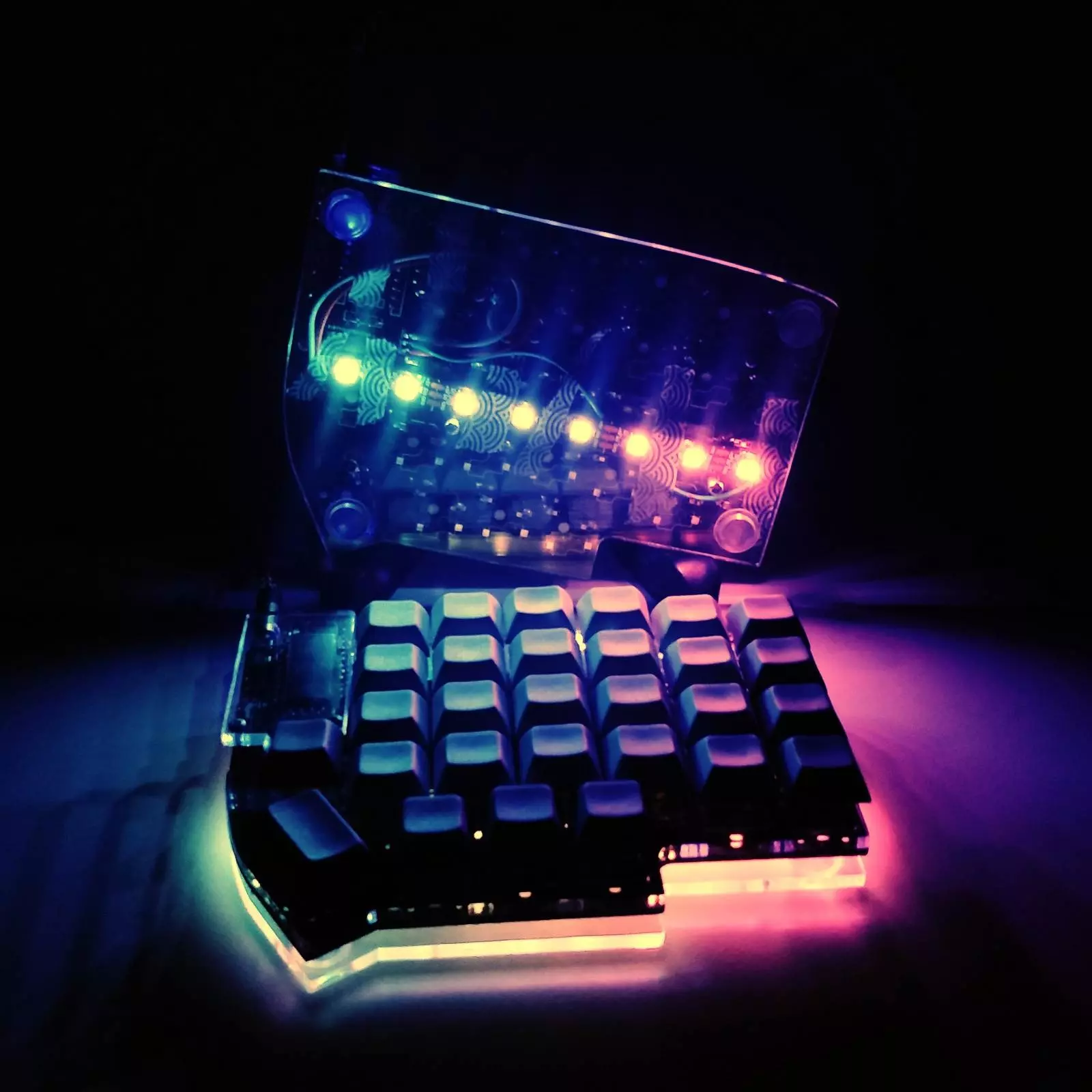
I added RGB underlighting to my Lily58 keyboard.

I installed the strip and even wrote most of this post during the turn and beginning of the year. Unfortunately, I’ve been busy with life and didn’t find the time to work on my blog. During my holiday, I finally took the time to finish this post; please enjoy the result!
Table of Contents
- Introduction
- Installation
- Firmware changes
- Fixing the right-hand-side OLED display
- Power consumption
- Closing thoughts
Introduction
I ordered a compatible RGB LED strip shortly after getting the keyboard, as I knew it’d take some time to arrive. The strip was this, but any 5V strip using WS2812B protocol or one of the other supported by QMK should work. My strip has a density of 60 LEDs per meter, it’s non-waterproof, and the PCB is black. Half a meter was more than enough for adding proper underlighting for my Lily58.
I had read some resources before starting the process, most notably Matt Pearce’s blog post. I could be sure I’m doing everything as I should and could focus on fixing the issues I encountered instead of figuring out how RGB lighting should be installed and configured.
This blog post aims to provide both an in-depth explanation for anyone planning to add underlighting to their keyboard as well as an overall description of the process. Thus, feel free to skip the parts that aren’t relevant to you.
Installation
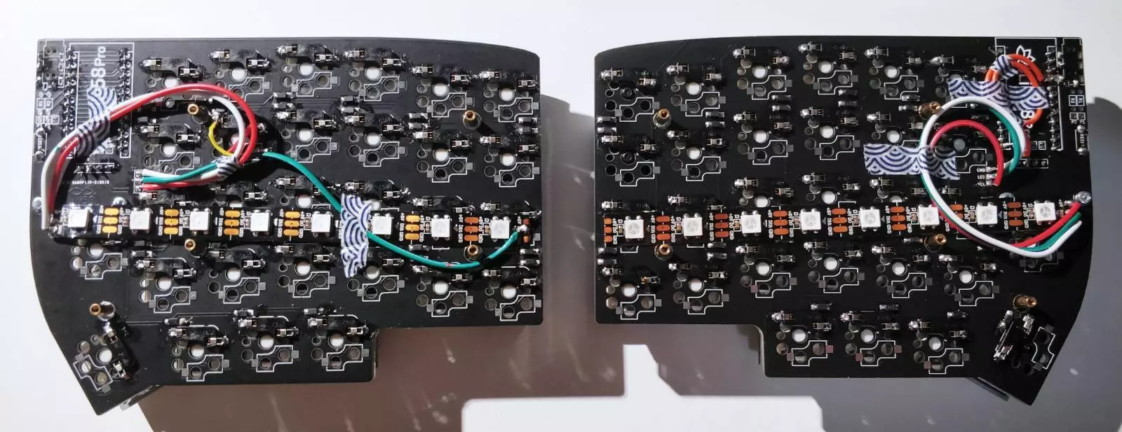
The installation of LED strips to Lily58 should be pretty straightforward. The keyboard has soldering contacts at the back of the PCB for the three required wires: voltage (5V), data, and ground.
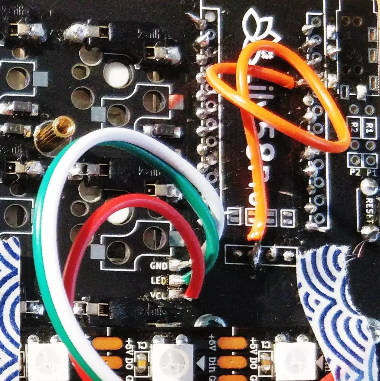
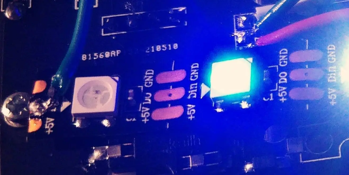
Both sides have individual installations, and I started with the right half of my keyboard. The strip came with connectors, which was nice, as wires were already soldered to both ends. I cut eight LEDs from both ends, ending up with two pieces with wires soldered and leaving a strip with 14 LEDs and no soldered connectors for possible later use. When I connected the strip’s wires to the keyboard and flashed the firmware with LED support (more on that later), nothing happened. I was sure that the configuration was at least somewhat correct, that the LED functionality was on, and that something should happen. After measuring the connections for a while using a multimeter, I found out that there was no voltage between the voltage and ground pins. I did some more measuring, and it seemed like only the voltage connection didn’t work, so I handwired the voltage to the strip directly from the microcontroller. That did the trick! Initially, I used some washi tape to secure the strip and wires to the PCB. Now the strips are secured by using their own adhesive.
For the left side, I had to desolder the data pin, as the data flows in one direction only. That wasn’t too big of a hassle, and the PCB connections for the strip worked straight away (after realizing and fixing the data pin issue 😅). Otherwise, the process was straightforward and way less stressful than the right half. I ended up turning the LED strip the other way around after realizing that some effects didn’t work just as expected. I could have avoided the mistake by following Matt’s blog post more carefully, but it was also easy to fix. Should I have already glued the strip, I probably could have reversed the LED order using QMK. Anyway, simply reversing the strip was a cleaner fix.
Firmware changes
The basic setup was straightforward, thanks to Matt’s configuration repository and QMK’s extensive documentation.
I set RGBLIGHT_ENABLE to yes in the rules.mk,
configured keymap.c to adjust the LEDs using the Adjust layer,
and finally let QMK know the details like the number of LEDs and what modes to include in config.h header file.
At this point, the LED strips worked and all, but tinkering with the firmware had just begun.
I was horrified to realize that the program memory of Elite-C would be full with just one or two animations enabled.
Having OLED displays and mouse keys enabled, the firmware is already quite full.
However, I noticed an optimization page from the QMK documentation.
A simple LTO_ENABLE = yes in my rules.mk file made it possible to include all of the predefined animations into the firmware for testing.
I wanted to have a control layer for the LEDs that could be toggled on and off. I thought that the Adjust layer would be perfect for the purpose, as in addition to toggling the layer, I could use it by holding down modifier keys. I couldn’t get toggling working for that layer, and after debugging for ages, I found out that it’s not possible to activate the Adjust layer without holding both Lower and Raise buttons, as it’s a tri-state layer. Well, time to create a new layer!
Creating the layer was easy, but it broke the current layer state indicator on the OLED display. I decided to modify the function used to transform the current layer to support my new keymap with added LED control layer. What I didn’t see coming was that I benefited from being familiar with bitwise operations, in this case, bit-shifting and bitwise or. I didn’t have to think of the logic much and got the right solution by copying the original code and just trying. Still, it was nonetheless valuable to understand what the different operations mean. My custom layer state reader, like my other keyboard source code, is available in my QMK repository.
Fixing the right-hand-side OLED display
The day after I successfully installed the LED strips to each half, I thought that the process of fixing the right-hand side OLED display would be pretty similar compared to the debugging process of the missing voltage.
I tested the PCB with a multimeter and concluded that only the voltage was missing from the OLED—the same issue as with the LED strip.
It turns out that the connection between the OLED and the LED strip voltage was fine, so I desoldered the led strip’s voltage wire from the microcontroller, soldered it to its intended place, and soldered a new wire from the VCC pin to the OLED’s VCC pin.
The fix can be seen in the picture above, where I showed the LED strip contact points.
It’s the orange wire between the header pins of the microcontroller and OLED.
![]()
Power consumption
Even though I mostly use the keyboard while my laptop is attached to a power source, I thought it would be nice to find out how much the LED strip affects the power consumption of the keyboard. I used a USB voltage and current meter and used values from that to calculate the power consumption.
| Description | U (V) | I (mA) | P (mW) |
|---|---|---|---|
| LEDs and OLEDs off | 5.04 | 50 | 250 |
| OLEDs on | 5.04 | 60 | 300 |
| LEDs minimum | 5.04 | 60 | 300 |
| Nice, basic LEDs | 5.04 | 70 | 350 |
| Colorful 50% brightness | 5.04 | 110 | 550 |
| LEDs full all | 4.99 | 470 | 2350 |
| LEDs full R | 5.01 | 240 | 1200 |
| LEDs full G | 5.01 | 240 | 1200 |
| LEDs full B | 5.04 | 210 | 1060 |
As one could guess, LEDs can affect power consumption enormously. Each channel consumes at max 150–180mA or 760–900mW, together 410mA or 2050–300mW. However, it was interesting to see that at a minimum level, there’s no noticeable increase in consumption and that moderate lighting doesn’t necessarily even double the consumption compared to normal usage. And well, the over 2-watt consumption is pretty high, and it may even be possible to detect some warming when blasting the LEDs at full intensity. There are multiple USB specifications with differing power limits, and one-watt consumption is allowed in all but the low-power specifications. Thus I don’t need to worry about draining too much power when plugging in my keyboard.
Closing thoughts
Underlighting was a great addition to the keyboard.
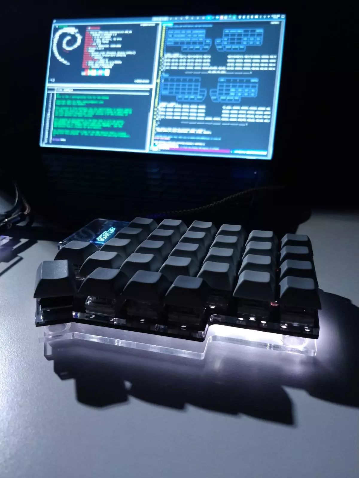
I like how it looks, and it can be easily toggled on and off when needed. There are still more customization possibilities. For example, I’ve thought of programming my own effect or just adding presets for my most used settings. It was super nice to get the OLED display of the right half to work as well; it maybe doesn’t bring much value, but now I don’t have to think that there’s something wrong with my keyboard. And, as always, it can be programmed to display anything.
Did you like this post?
I'll announce new posts in the following channels:
See my blog's front page to read my other posts.
You can reach me on Mastodon: @sampo@hachyderm.io. I'd love to hear from you!